Flashing an ENER-J SHA5264 wifi smart plug to Tasmota
This was originally a gist posted here 4 years ago.
I have removed references to tuya convert as it hasn’t worked for a long time now. You should be able to flash it with a serial adapter connected to the test points though. If you plan to do this it would be a good idea to buy just one SHA5264 to check they still use an ESP8266 chip as most Tuya devices have switched to Beken chips.
While looking at home automation with a particular interest in local control with Home Assistant I thought I would have a look at a smart socket with energy monitoring. At the time this particular model didn’t have an entry on the Tasmota device templates repository nor was it listed as not compatible. I thought I would take a chance on it being ESP8266 based, the screws in the case also suggested it could be opened without damage in case it required serial flashing or a multimeter to work out how the energy monitoring chip was connected which is very helpful and saves destroying a plug for science.
TL;DR
The plug is Tuya based and can be opened non destructively and flashed with a serial adapter using test points, the pinout and device template for this power monitoring plug:
- GPIO0 Button 1
- GPIO4 BL0937 CF
- GPIO5 HLWBL CF1
- GPIO12 HLWBL SEL_i
- GPIO13 LED 1
- GPIO14 Relay 1
{“NAME”:”ENER-J SHA5264”,”GPIO”:[32,0,0,0,2720,2656,0,0,2624,288,224,0,0,0],”FLAG”:0,”BASE”:18}
A peek inside
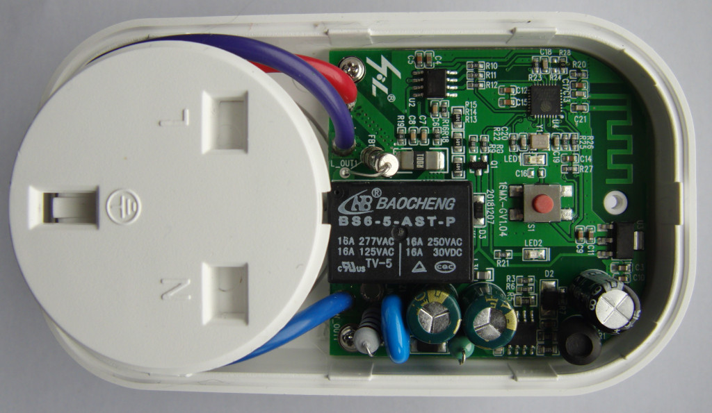
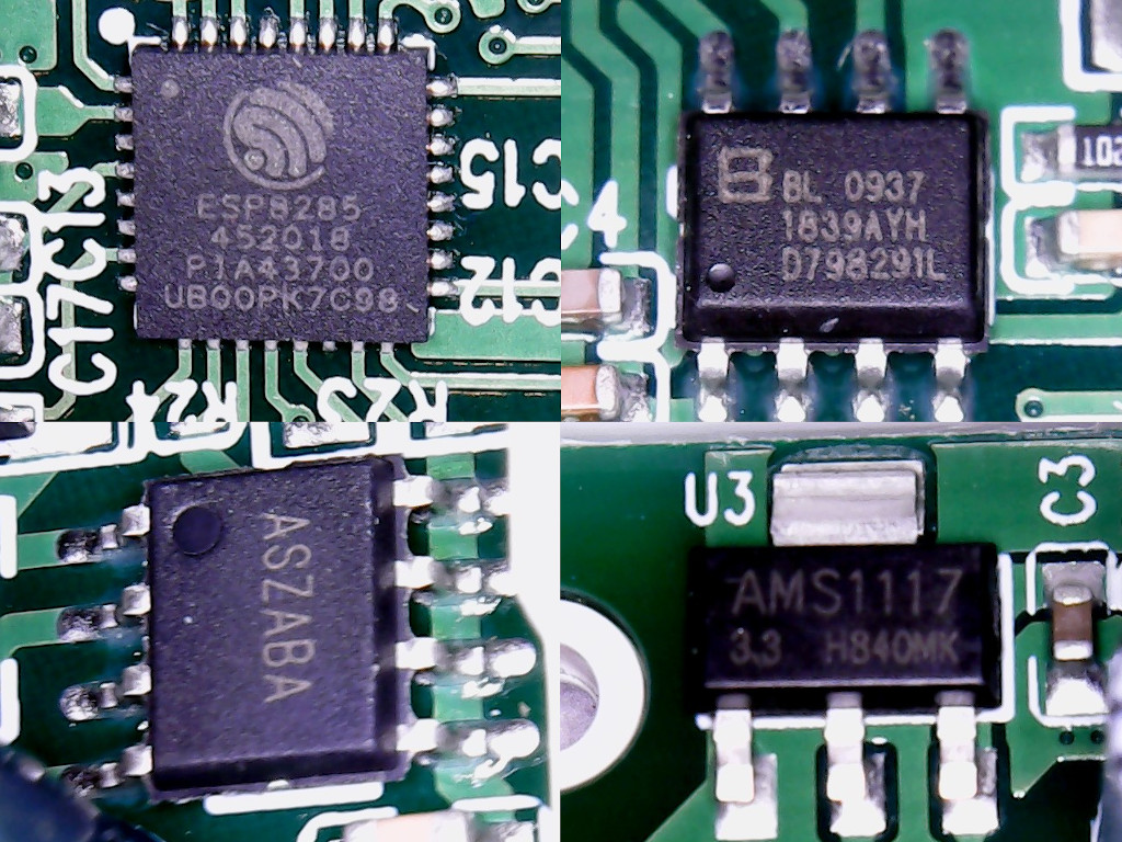
As soon as the Plugs arrived I opened one up to have a peek inside and see if the plug was a candidate to convert to Tasmota. Removing 3 screws and the cover revealed an ESP8285 chip, A Shanghai Belling BL0937 energy meter chip and a power supply consisting of a Silergy SY50282 Buck converter and an AMS1117 regulator
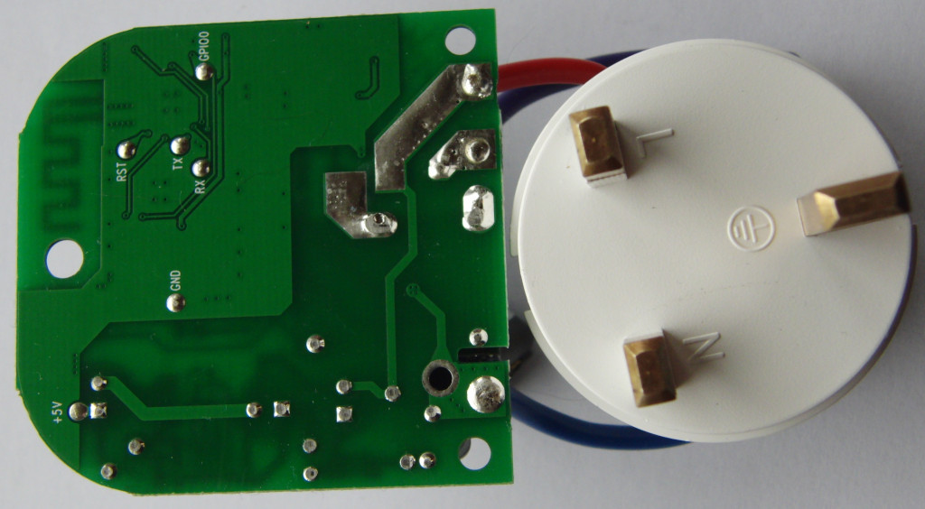
Looking at the back of the PCB reveals test points for 5v, GND, Tx, Rx, RST and GPIO0 so it should be possible to flash this using a serial interface.
Reflashing the firmware
There were already 2 ENER-J devices listed on the tasmota device templates repository and both of those were listed as Tuya based which suggested that all the ENER-J Wi-Fi devices would be based on that platform. When this was originally written tuya-convert worked but that was fixed years ago now and I don’t expect it would work with a newly purchased device so it will require flashing using a serial cable:
Do NOT plug the socket into the mains while flashing the device with a serial cable!
- With the socket unplugged unscrew the cover and solder a usb to TTL adapter to the test points on the board More info here
- Using Tasmotizer or the Tasmota web installer install the tasmota firmware.
- Once flashed desolder the serial wires and put the socket back together and screw the case together and plug it in.
- The plug will now appear as an access point so connect to this network and open the webpage at 192.168.4.1 and configure the plugs Wi-Fi credentials.
- Connect back to your network and open the devices webpage.
- Open up the “Configuration” > “Configure Other” page and paste in the Template {“NAME”:”ENER-J SHA5264”,”GPIO”:[32,0,0,0,2720,2656,0,0,2624,288,224,0,0,0],”FLAG”:0,”BASE”:18}
- Finally calibrate the power monitoring chip I used a toaster and a plug in power meter that showed voltage, current and watts and calibrated the plug to that power meter.
- Your plug should now work
This isnt really meant to be a how to, more a description of what I did so its possible I missed a step or didn’t describe it well so for more information see the Tasmota documentation for authoritative information on flashing and using Tasmota.
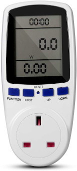
The type of power meter I used to calibrate the plug. I plugged this into the wall, then the smart plug into that and finally the toaster into the smart plug so i could calibrate the smart plug to the energy meter, initally the smart plug was way off reporting a voltage of 294v and a current of 3.9A when the power meter was showing 241V and 3.5A, after calibrating it matched the power meter and showed a power factor of 1.0 which is what you would expect of a toaster which is a purely resistive load.
Woah there where did that template come from
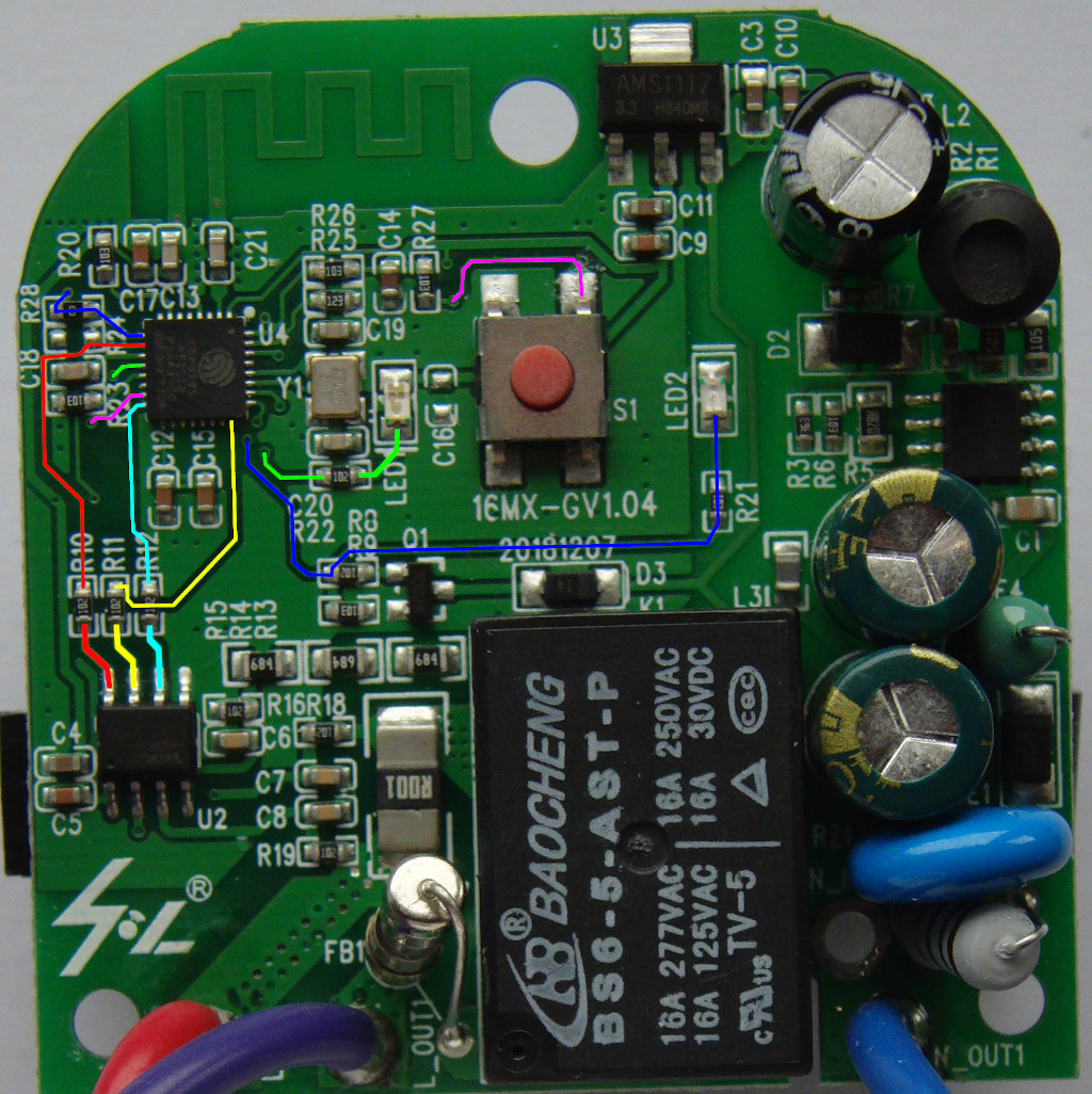
Since this plug can be easily opened without damage I used a multimeter to trace out the connections, annoyingly all the gpio’s seem to have 1K current limiting resistors in series so you cant just use continuity check from the power meter chip to the ESP8285, you have to meter from pin to resistor then from the other side of the resistor to the ESP, some time spent squinting at the board and testing continuity gave the connections as:
- GPIO0 Button 1
- GPIO4 BL0937 CF
- GPIO5 HLWBL CF1
- GPIO12 HLWBL SEL_i
- GPIO13 LED 1
- GPIO14 Relay 1
Initially I set GPIO12 as HLWBL SEL but that produced nonsense readings with a voltage of 0V when the plug was switched on as it was reading current as voltage, using the inverted output fixed this. This resulted in a device template of:
{“NAME”:”ENER-J SHA5264”,”GPIO”:[32,0,0,0,2720,2656,0,0,2624,288,224,0,0,0],”FLAG”:0,”BASE”:18}